Accessing the CLI via PuTTY with a Console Connection
Step 1. Connect the switch to the computer using a standard 9-pin serial cable.
The Cisco DB9 to RJ45 Console Cable also supports console connections, but only if the switch has an RJ45 Console port. An RJ45 Console port resembles an Ethernet port and is labeled CONSOLE on the back of the switch.
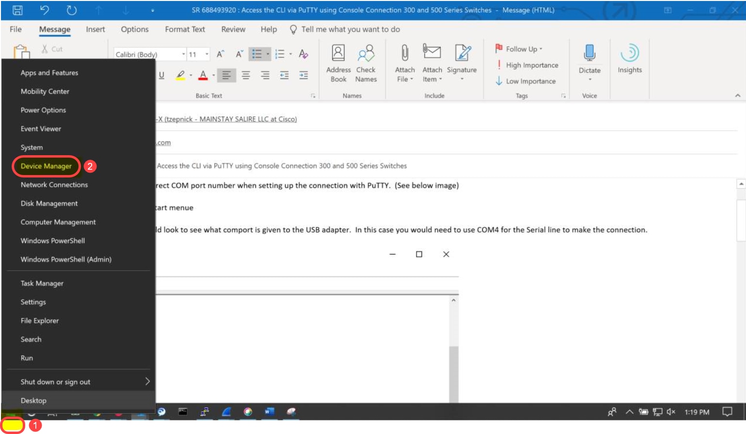
Newer laptops don’t have Serial ports on them, so in this case you have to use a USB to Serial adapter. When plugging that into a computer it assigns a COM port number to it that is not COM1. If this is the case for you, you need to know where to look to find the correct COM port number when setting up the connection with PuTTY. Right-click on the Windows logo/Start menu and click on Device Manager to open it.
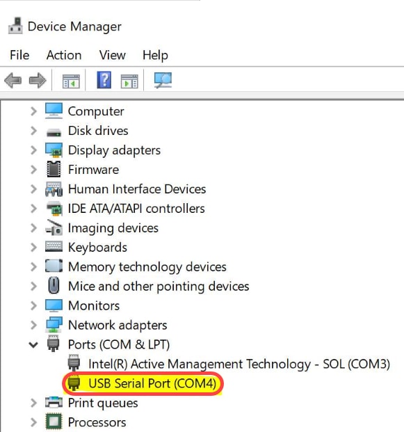
In the Device Manager, you would look to see what COM port is given to the USB adapter. In this case you would need to use COM4 for the Serial line to make the connection.
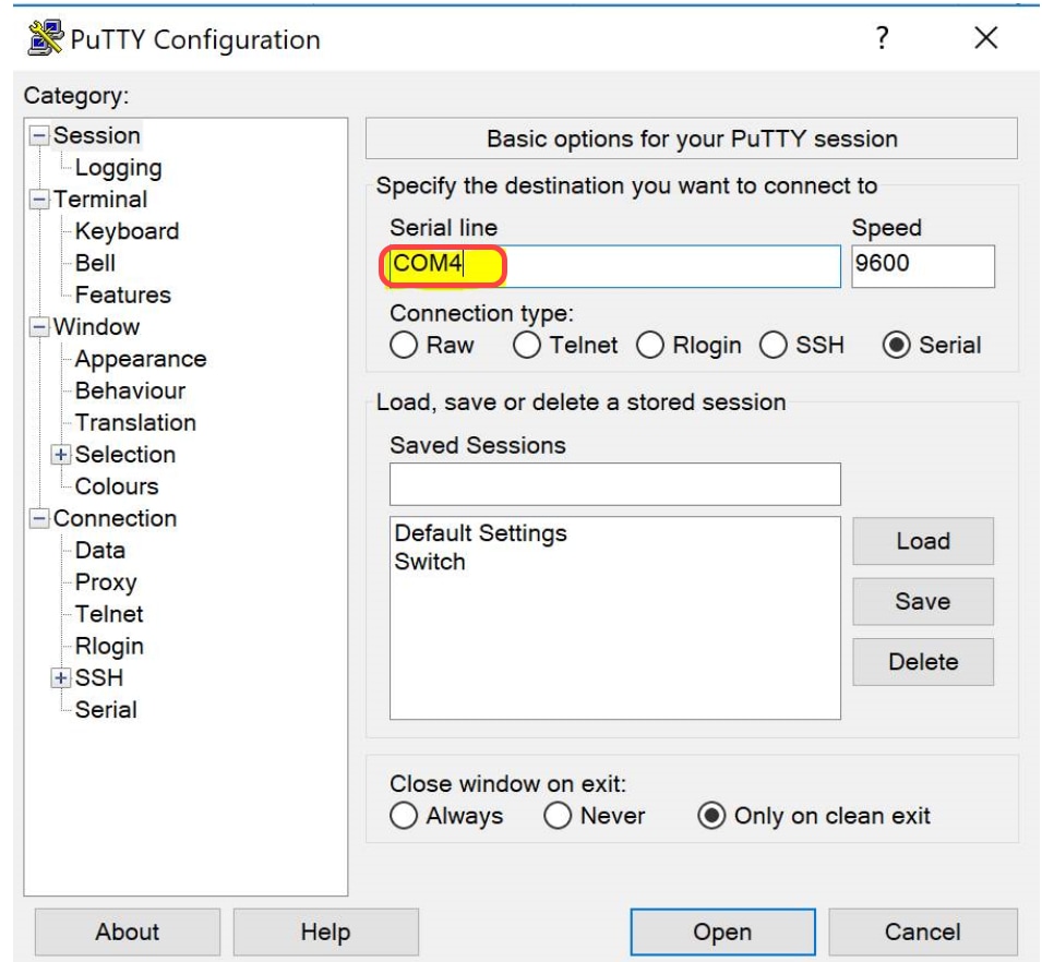
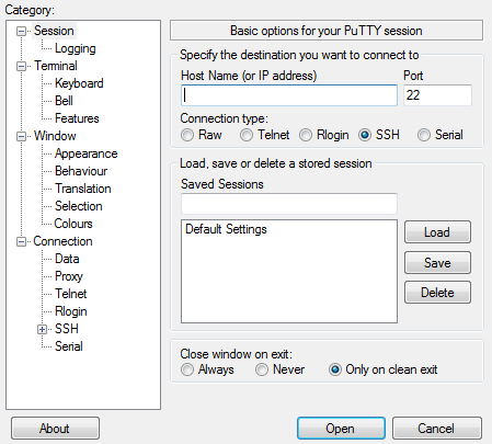
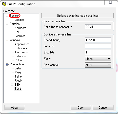
Step 2. Open the PuTTY application. The PuTTY Configuration window opens:
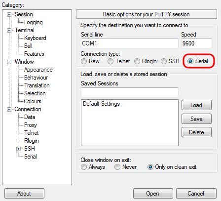
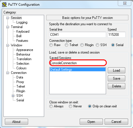
Step 3. Under the Connection Type field, click the Serial radio button.
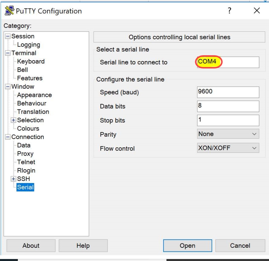
Step 4. In the Category navigation field, choose Serial.
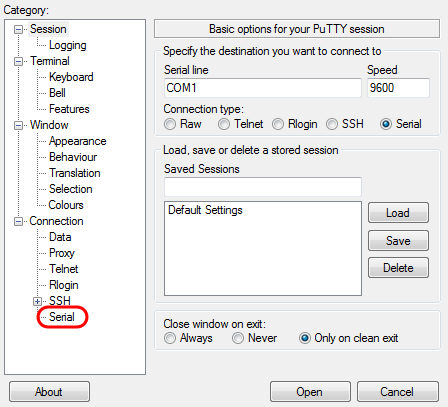
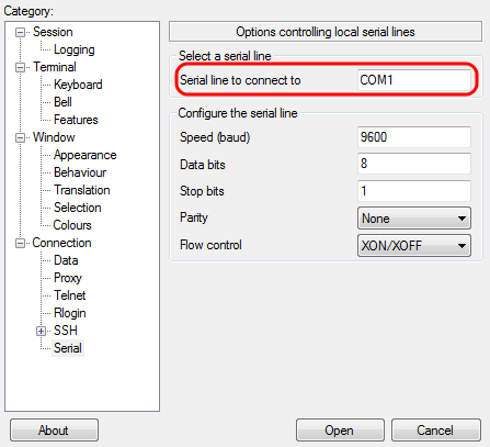
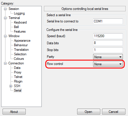
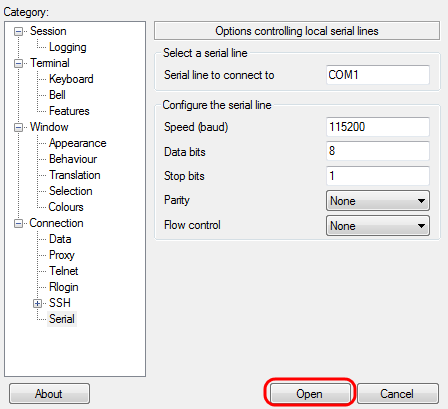
The Options controlling local serial lines page opens:
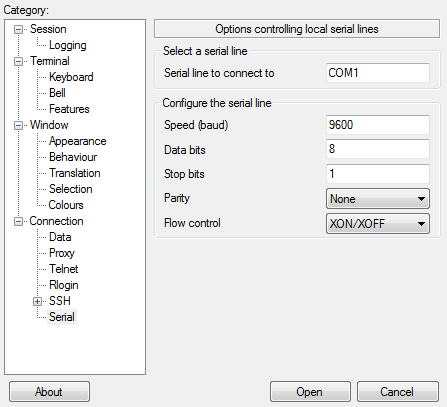
Step 5. In the Serial line to connect to field, enter the COM port that your device is connected to. The default COM port is COM1.
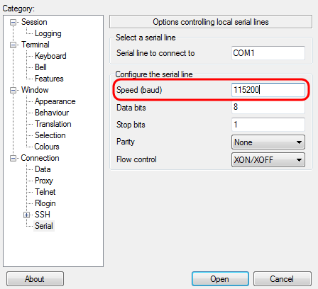
Step 6. In the Speed (baud) field, enter the digital transmission speed that is compatible with the switch. For 300 and 500 Series Managed Switches, the speed must be set to 115200.
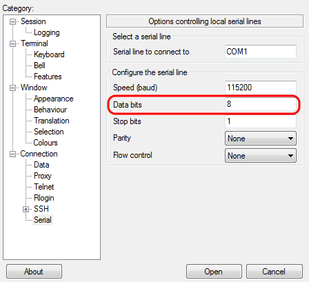
Step 7. In the Data bits field, enter the number of data bits used for each character. The recommended value is 8.
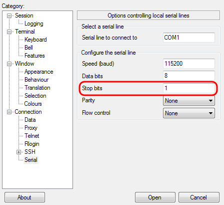
Step 8. In the Stop bits field, enter the number of bits to be sent at the end of every character. The stop bit informs the machine that it has reached the end of a byte. The recommended value is 1.
Step 9. In the Parity drop-down menu, select the method of detecting errors in transmission. The recommended method for detecting errors in transmission is None.

Step 10. In the Flow Control drop-down menu, select the method of preventing data overflow. The recommended method for preventing data overflow is None.
Step 11. (Optional) In order to save the connection settings for future use, go to the Category navigation pane and choose Session. If you do not wish to save the connection settings, skip to Step 14.
Step 12. Under the Saves Sessions field, enter a name for the settings to be saved as.
Step 13. Click Save.
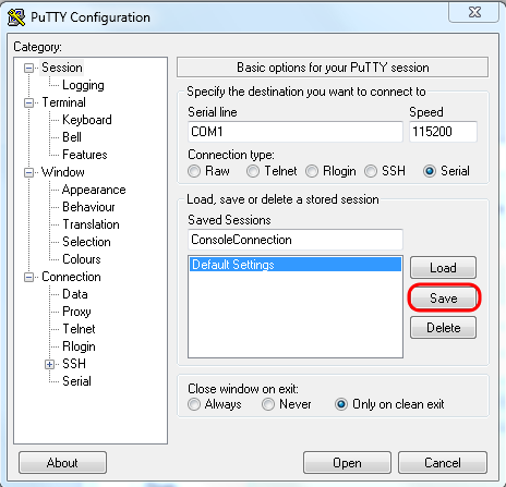
Step 14. Click Open.
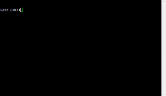
The COM1 – PuTTY console window opens.
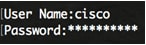
Step 15. Hit Enter on the keyboard to activate the Command Line Interface (CLI). The log in prompt is displayed:
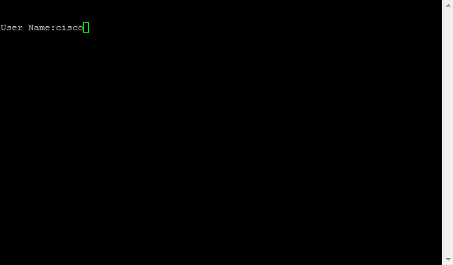
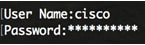
Step 16. Enter the User Name. The default username is cisco.
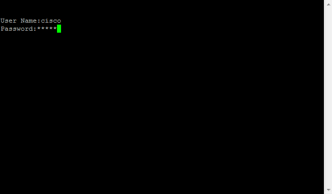
Step 14. Enter the Password. The default password is cisco.
reference
https://www.cisco.com/c/en/us/support/docs/smb/switches/cisco-small-business-300-series-managed-switches/smb4984-access-the-cli-via-putty-using-a-console-connection-on-300-a.html
CLI를 사용하여 스위치에서 IP 주소 설정 구성
CLI를 통해 스위치의 IP 주소 구성
중요: 스위치가 대기 스위치가 있는 스태킹 모드 중 하나에 있는 경우 스태킹 활성 전환 중에 네트워크에서 연결을 끊지 않도록 고정 IP 주소를 구성하는 것이 좋습니다. 스탠바이 스위치가 스택을 제어할 때 DHCP를 사용할 때 스택의 원래 액티브-지원 유닛에서 받은 것과 다른 IP 주소를 받을 수 있기 때문입니다.
고정 IP 주소 구성
이 시나리오에서는 DHCP 서버의 가용성 없이 스위치가 설정됩니다. 스위치에서 고정 IP 주소를 구성하려면 다음 단계를 수행합니다.
1단계. 직렬 케이블을 사용하여 컴퓨터를 스위치에 직접 연결합니다.
스위치에 SSH를 추가하려는 경우 여기를 클릭하여 스위치에 대한 CLI 액세스 권한 부여에 대한 문서를 확인하십시오.
2단계. 스위치 콘솔에 로그인합니다. 기본 사용자 이름 및 비밀번호는 cisco/cisco입니다. 새 사용자 이름 또는 비밀번호를 구성한 경우 대신 자격 증명을 입력합니다.
3단계. 스위치의 Privileged EXEC 모드에서 다음을 입력하여 Global Configuration 모드로 들어갑니다.
SG350X#configure4단계. Global Configuration 모드에서 다음을 입력하여 인터페이스 컨텍스트를 입력합니다.
SG350X(config)#interface [interface-id | vlan-id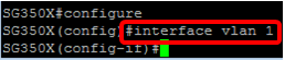
5단계. 다음 중 하나를 입력하여 인터페이스의 IP 주소를 정의하려면 IP 주소 인터페이스 컨피그레이션 명령을 입력합니다.
- ip 주소 [ip-address] {{mask | prefix-length}}— reload 명령을 사용하여 스위치를 즉시 다시 로드합니다.
- ip 주소 [ip-address] {{mask | prefix-length}} [default-gateway-ip-address] — {{hh:mm 다시 로드를 사용합니다. | mm | at hh:mm [day month]} 명령을 사용하여 예약된 스위치 다시 로드를 지정합니다.
옵션은 다음과 같습니다.
- ip address — IP 주소를 지정합니다.
- mask — IP 주소의 네트워크 마스크를 지정합니다.
- prefix-length — IP 주소 접두사를 구성하는 비트 수를 지정합니다. 접두사 길이 앞에는 슬래시(/)가 와야 합니다. 범위는 8~30입니다.
6단계. (선택 사항) 인터페이스에서 IP 주소를 제거하려면 다음을 입력하여 no 형식의 IP address 명령을 사용합니다.
SG350X(config-if)#no ip address7단계. end 명령을 입력하여 스위치의 Privileged EXEC 모드로 돌아갑니다.
SG350X(config-if)#end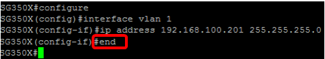
8단계. (선택 사항) 인터페이스에 IP 주소 컨피그레이션 및 정보를 표시하려면 Privileged EXEC 모드에서 다음 명령을 입력합니다.
SG350X#show ip interface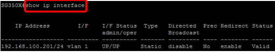
9단계. (선택 사항) 구성된 설정을 시작 구성 파일에 저장하려면 다음을 입력합니다.
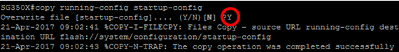
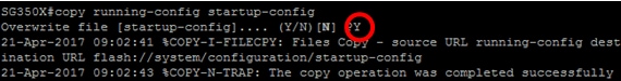
SG350X#copy running-config startup-config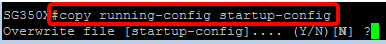
10단계. (선택 사항) Overwrite file [startup-config]... 프롬프트가 나타나면 키보드에서 Yes 또는 N을 No로 누릅니다.
이제 스위치의 고정 IP 주소 설정을 구성했어야 합니다.
DHCP를 통해 IP 주소 구성
이 시나리오에서는 스위치가 활성 DHCP 서버 역할을 하는 라우터에 연결됩니다. DHCP를 통해 스위치의 IP 주소를 구성하려면 다음 단계를 수행합니다.
1단계. 직렬 케이블을 사용하여 컴퓨터를 스위치에 직접 연결합니다.
2단계. 스위치 콘솔에 로그인합니다. 기본 사용자 이름 및 비밀번호는 cisco/cisco입니다. 새 사용자 이름 또는 비밀번호를 구성한 경우 대신 자격 증명을 입력합니다.
3단계. 스위치의 Privileged EXEC 모드에서 다음을 입력하여 Global Configuration 모드로 들어갑니다.
SG350X#configure4단계. Global Configuration 모드에서 다음을 입력하여 인터페이스 컨텍스트를 입력합니다.
SG350X(config)#interface [interface id | vlan-id]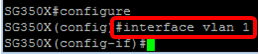
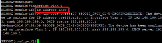
5단계. 인터페이스 컨텍스트에서 다음을 입력하여 DHCP 서버에서 IP 주소를 얻습니다.
SG350X(config-if)#interface [interface id | vlan-id]지정된 인터페이스에 디바이스가 구성되었다는 알림이 표시됩니다.
6단계. (선택 사항) 인터페이스에서 IP 주소를 제거하려면 다음을 입력하여 IP 주소 DHCP 명령의 no 형식을 사용합니다.
SG350X(config-if)#no ip address dhcp7단계. end 명령을 입력하여 스위치의 Privileged EXEC 모드로 돌아갑니다.
SG350X(config-if)#end8단계. (선택 사항) 인터페이스의 IP 주소 컨피그레이션 및 정보를 표시하려면 Privileged EXEC 모드에서 다음 명령을 입력합니다.
SG350X#show ip interface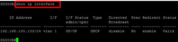
9단계. (선택 사항) DHCP 클라이언트 인터페이스에 IP 주소 컨피그레이션 및 정보를 표시하려면 특권 EXEC 모드에서 다음 명령을 입력합니다.
SG350X#show ip dhcp client interface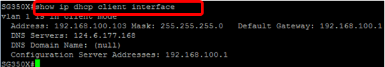
10단계(선택 사항) 구성된 설정을 시작 구성 파일에 저장하려면 다음을 입력합니다.
SG350X#copy running-config startup-config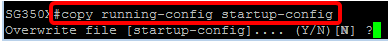
11단계. (선택 사항) Overwrite file [startup-config]... 프롬프트가 나타나면 키보드에서 Yes 또는 N을 No로 누릅니다.
이제 스위치에서 DHCP IP 주소 설정을 구성했어야 합니다.
reference
https://www.cisco.com/c/ko_kr/support/docs/smb/switches/cisco-350-series-managed-switches/smb5557-configure-the-internet-protocol-ip-address-settings-on-a-swi.html
Comments
Post a Comment